VFX Shader Editor
Description
Node-based shader prototype tool for visual effects creation as my final bachelor's thesis in Game Development at CITM, UPC.
The project development wrapped up with a framework focused on creation and prototyping of shaders with a self-made node graph editor. The final release comes with 16 available nodes along the master one in order to recreate a bunch of shaders from simple to advanced functionalities.
In Addition, this tool includes a ShaderLab code translator to provide support in export Unity shader file format from the tool.
Shader Showcase
Demo Tech
Thesis Presentation
Starting Point

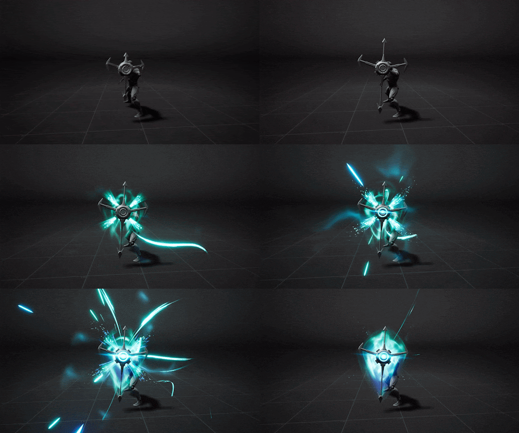
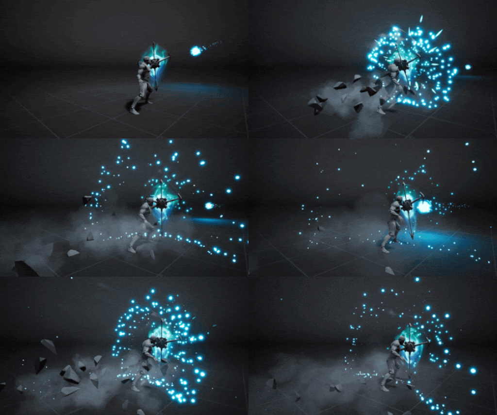
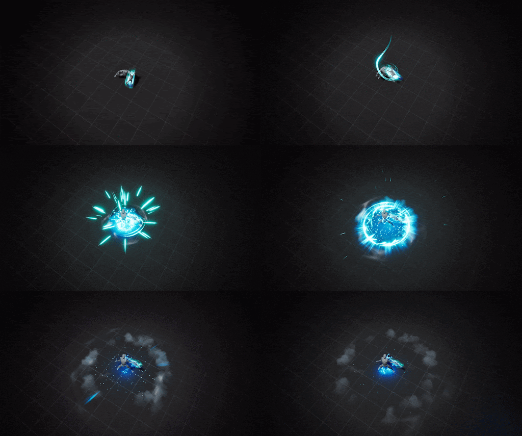
VFX from Thomas Francis
If we analyze carefully, we can see that Thomas uses a combination of green and blue colors, plays a lot with transparency, manipulates the textural coordinates that this energy animation generates and among other techniques achieves this result.
All this magic is possible thanks to what are known as shaders!
Shaders are code instructions executed on the GPU that allow the rendering and manipulation of the final color of each pixel so they can generate any visual content, from shading a surface to producing complex visual effects.

OpenGL and DirectX are very popular graphic libraries that allow the programming of these shaders thanks to languages implemented by them such as GLSL, HLSL, etc.
Today there are several technology companies whose software allows the creation of shaders without having to touch code where we find the Unity's ShaderGraph or the Unreal Material Editor.
Goal
That said, my project consists of producing an adaptation of the existing solutions in products such as unity or unreal engine, but simplifying it to a tool flexible, oriented exclusively to the creation of shaders using a node-based ui and that allows rapid prototyping from the first sketches to the final visualization.
For this I want to use the example of Tiled, an application focused on the creation of levels and maps in 2D, free and where many companies bet on Tiled for the levels of their games, especially those that cannot afford commercial graphics engine licenses.
One of the last games made in Tiled is carrion.
Project Set-Up
Let's talk more about the project itself and its development from start to completion.
The project starts from a base structure or skeleton using the behavioral design pattern template method, which defines an algorithm from a superclass (module) and whose subclasses share the same structure but perform different tasks by overwriting the steps of the algorithm.
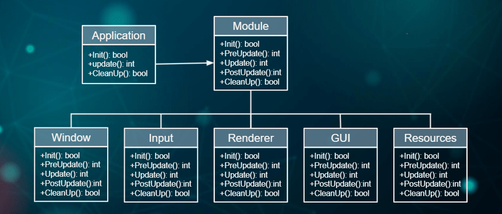
For the correct use of this algorithm, the auxiliary class application is necessary since it contains all those subclasses and keeps them running.
This is known as a controlled loop or game loop which would begin with the initialization of the subclasses, the update where they would remain in constant execution doing their tasks and rendering on the screen, and finally the cleanup during the closing of the application.
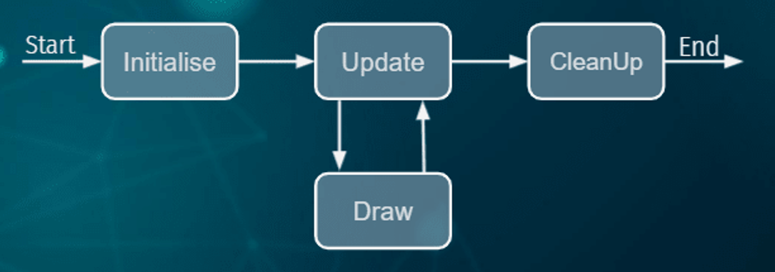
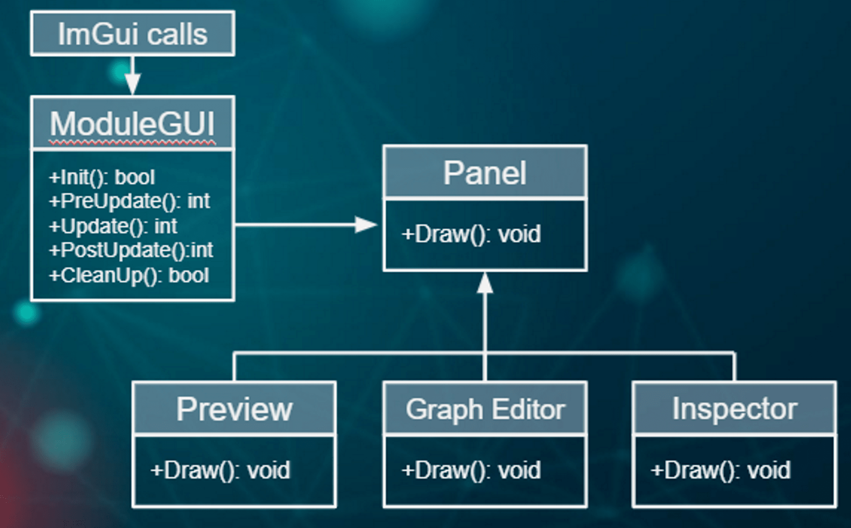
In the case of my project, it would be represented with the following diagram.
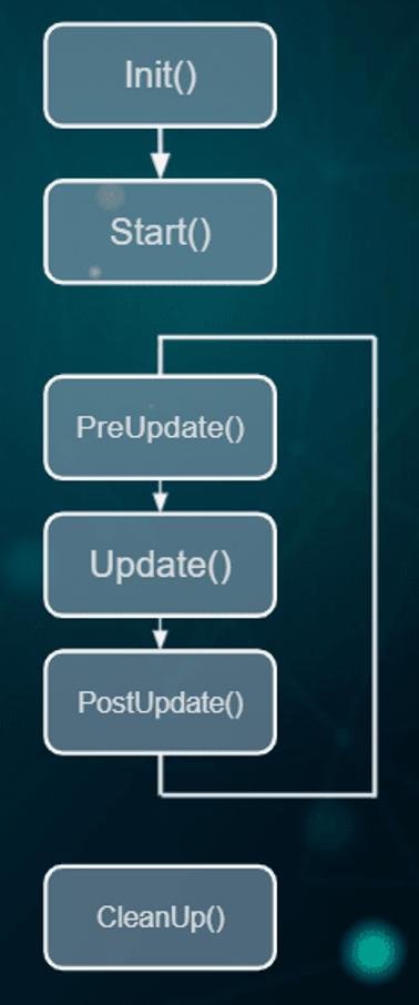
From here, a pipeline renderer is implemented with a very basic shader system, which starts from the resource module with the ability to create shader resource-type objects derived from the parent class resource.
In this way, the information and functionalities of the shaders are encapsulated, such as file reading, compilation, etc., and their serialization to external files.
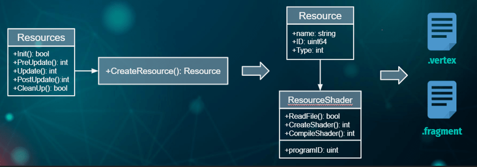
At this point we already generate our first shaders, with this and the help of libraries such as GLEW that make geometry rendering possible, we prepare a scene with a grid as a plane and a quad thanks to the shader system.
In addition we would also have other libraries such as sdl that mainly handles keyboard and mouse input, mgl for mathematical operations and pcg for procedural generation of ids
As for the UI system, very simple from the module it acts as an auxiliary class of the panel entity since it contains and executes the tasks carried out by its child classes.
In our case, the preview panel that shows the results is included in the application, the graph editor panel which is the canvas where the shaders would be created and edited, and the inspector where the individual information of each element of the canvas would be displayed. Of course all this thanks to imgui.
Node Graph Editor
There were different ways to approach this goal, but in the end I decided to create my own nodal system.
the implementation begins with the creation of the shadergraph class, which contains two main elements, the nodes and their connections. This class manages the logic of these elements where the input () function would check and process the input received from nodes and connections, the draw () function renders these elements according to their states and finally the postupdate () function that is responsible for eliminating said nodes and connections if their status is as indicated.
In general, this would be the diagram that would represent the flow control of the nodes and connections.
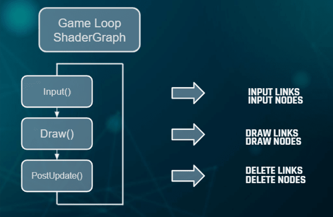
To explain it in a more technical way, here we would have the shadergraph class that we mentioned, with its mentioned functions and which, as I said, would have both a list of its nodes (shadernode) and a list of its connections (shaderlink).
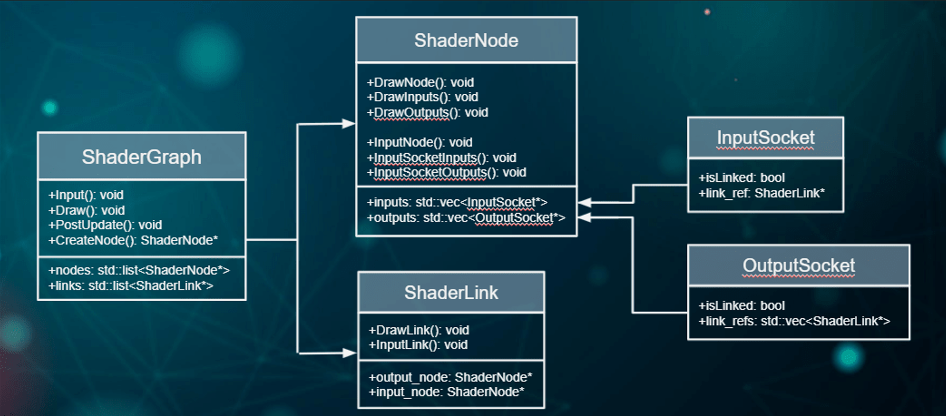
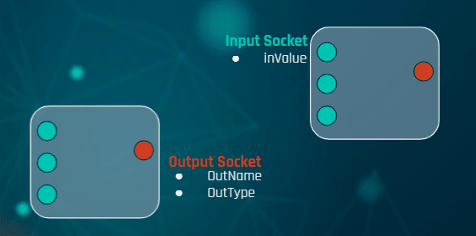
ShaderNode is the class that encapsulates all the information of the node element, here we would have a mockup of what a node would be with its inputs in green and its output in red.
This is because each node contains a collection of its inputs and its outputs as we can see. Both the node and its sockets have their functions in charge of rendering them and processing inputs.
On the other hand we would have the connections, here we would have it in the mockup, which are connected between sockets and that is why it has two node type pointers, one is the one that comes from an output and the other from an input. In addition, it also has its rendering and input processing functionalities.
Finally, the sockets of the nodes also represent classes where information such as the numerical value of the node or references of the connection from which it is linked is encapsulated.
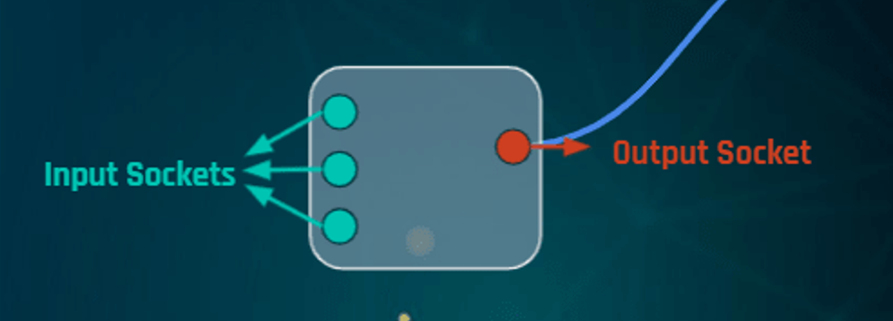
Visual Example of node with its sockets
Once implemented, here we would have the first results, on the one hand the node with its sockets and its bar with the title of the node. In the following image you can see those nodes created in the panel canvas connected between them.
Node Library
Well, at this point it's time to show the entire catalog of nodes that had been implemented during the development to achieve those similar techniques and effects that we have seen from Thomas Francis.
The following list displays all the nodes tidy up by categories.
Constant
- Float Node
- Vector2 Node
- Vector3 Node
- Vector4 Node
- Color Node
- Time Node
Math
- Add Node
- Substract Node
- Multiply Node
- Divide Node
Texture
- Texture Node
- Texture Sampler Node
Geometry
- UV Node
- Tiling & Offset Node
- Panner Node
- Parallax Oclussion Node
Master
-
Unlit
- Opaque
- transparent
GLSL Abstraction
Now that we have the system of nodes and the catalog of nodes, it is necessary to explain how these geometric elements have been abstracted into fragments of glsl code, because after all, the shader is still code instructions that can be stored in a string type variable.
That is why the key to all this is that the data that each node saves and transmits is of type string.
Here in this example the main idea that I want to understand is that the outputs of each node always save the name of the node because when this node is interlaced with another it will be able to transmit that name as the name of the variable it represents in order to make the pertinent calculations at the posterior node.
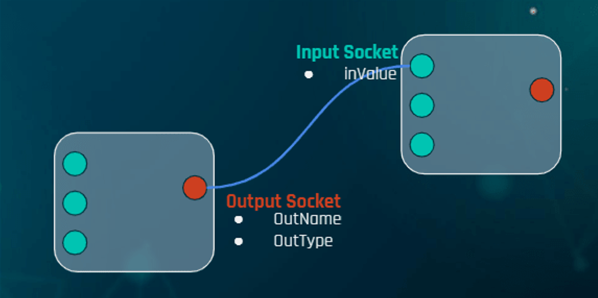
With which each node has in one place the declaration in glsl of that variable, that way we already have the variable in the code and in another place its subsequent definition with the assigned value that receives all this in chain from its input as well.

Where does this inValue come from? Well, in the case that two nodes are connected, the invalid corresponding to the name of the variable of the node to which it is connected from its output socket, hence the importance of the name.
In the case that the nodes are not connected, each of these nodes contains a numerical value, editable from the application details panel and which is subsequently transpor- ted into a chain to respect the procedure.
Once we have each node with its information in glsl, it only remains to join all the pieces in the shader that we already had, for this shader compiler is a class that is responsible for managing this merge starting from the main node (master) from which recursively you travel to the final node that has no connections in its inputs to have all the declarations and definitions of variables and functions of each node in order and add them in the corresponding areas of the shader so that it can compile correctly.
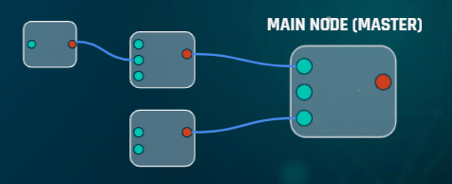
Then simply recompile the shader with the new changes to have the updated id and overwrite the external files that we already had previously.
Unity Exporter
Finally, the last point is to support the export of shaders generated in external applications, in the case of the project in Unity.
To achieve this, it was decided to implement a glsl to shaderlab language converter, the declarative language that Unity uses to generate its shaders as assets.
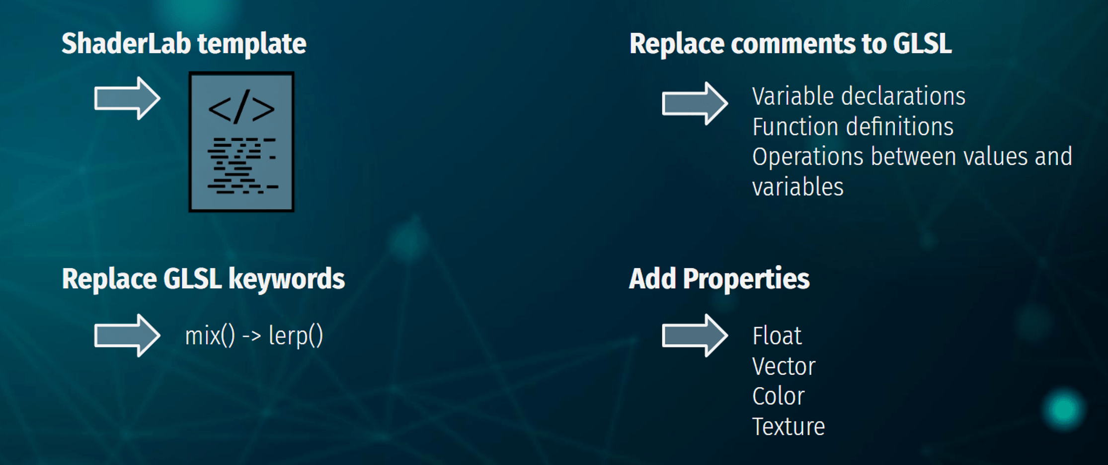
The first step is to have a template established with the base structure of shaderlab, all stored in a string. The second step is to replace some comments located in key areas of the template to add what would be declarations, definitions, etc.
Then it would come to replace all those keywords that hlsl does not have support because they have another name, an example would be the keyword mix that its counterpart in hlsl is lerp (). and finally add definitions in the properties section so that unity detects them as editable variables from the material in the graphics engine.
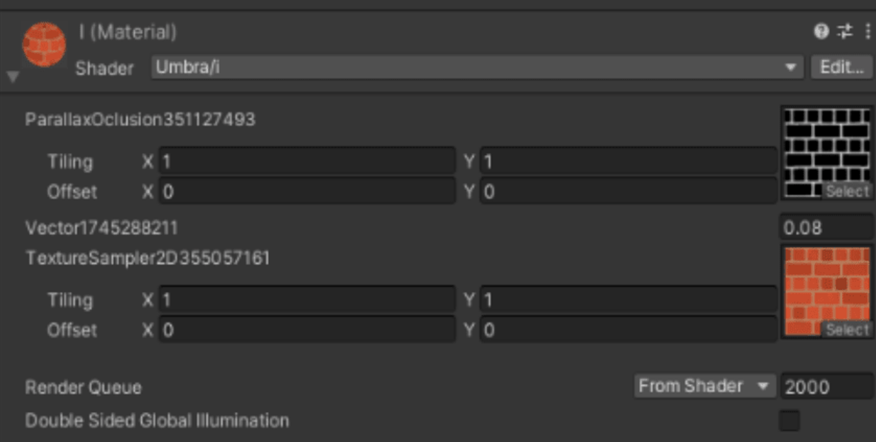
As a final result we would have that once we have the shader created, we give the export button and from this directory that appears on the screen we would have the shader in a format that has unity and it would only be drag it to unity and it automatically becomes a shader type asset that can be used on any material.
As can be seen, some variables are converted to properties so they can be modified in the material.

 Carlos Peña


